 CN
CN
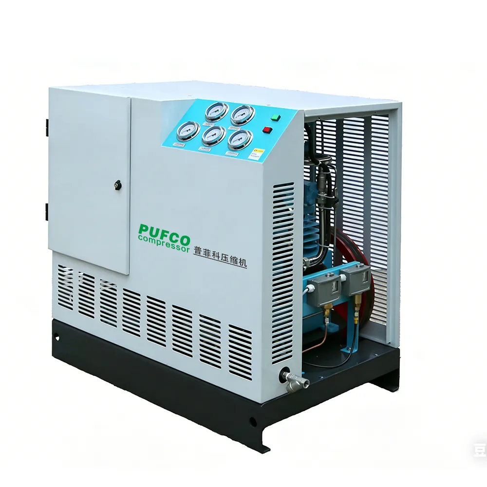
Centrifugal Air Compressor Definition and Core Industrial Role
A centrifugal air compressor is a dynamic machine that pressurizes air by converting kinetic energy into static pressure. It uses a high-speed rotating impeller to accelerate air outward, then slows the air in a diffuser to build pressure. Unlike positive displacement compressors, centrifugal units deliver continuous, high-volume airflow with inherently oil-free output—making them ideal for demanding industrial operations. These compressors serve as the backbone of large-scale manufacturing, oil and gas facilities, chemical plants, and power generation. Their ability to run 24/7 with relatively high energy efficiency makes them essential for processes requiring steady, clean compressed air. While initial investment and maintenance costs are higher, their capacity for handling massive air demands justifies the expense in heavy industry.
How a Centrifugal Air Compressor Works: Kinetic to Static Pressure Conversion
The operation of a centrifugal air compressor relies on a two-step process that converts kinetic energy into static pressure: first, the impeller accelerates the air; then, stationary components decelerate it to build pressure. This dynamic principle enables continuous, high-volume delivery—critical for large-scale industrial applications.
Impeller acceleration and centrifugal energy transfer
Air enters the compressor at the center of a rapidly spinning impeller. As the blades rotate, centrifugal force flings the air outward toward the impeller’s edge, significantly increasing its velocity and converting mechanical energy from the drive shaft into kinetic energy. The high-speed rotation also creates a low-pressure zone at the inlet, drawing in more air to sustain steady flow. Because lubrication is fully isolated within the bearings—no oil contacts the airstream—the process is inherently oil-free. Impeller design determines maximum velocity, and multi-stage configurations use additional impellers to raise pressure incrementally. This method is especially well-suited for applications requiring large, uninterrupted volumes of compressed air.
Diffuser and volute design: Applying Bernoulli’s principle for pressure rise
After exiting the impeller, high-velocity air enters the diffuser—a precisely contoured stationary passage. Per Bernoulli’s principle, as the air slows, its kinetic energy transforms into static pressure. The diffuser’s gradually widening cross-section forces deceleration while minimizing turbulence and losses. Next, the volute—a spiral-shaped housing—collects air from around the impeller perimeter and directs it toward the outlet. Its expanding geometry further reduces velocity and stabilizes pressure. Together, the diffuser and volute complete the kinetic-to-static conversion. Without these stationary components, a single impeller could not achieve meaningful compression—speed alone does not equal usable pressure.
Essential Components of a Centrifugal Air Compressor
Understanding the internal architecture of a centrifugal air compressor is crucial for proper selection and maintenance. The system is divided into two core groups: the rotating assembly and the stationary flow path, supported by critical auxiliary systems that ensure reliability, efficiency, and safety.
Rotating assembly (impeller, shaft) and stationary flow path (diffuser, volute, IGVs)
The rotating assembly consists of the impeller and shaft. The impeller—typically forged from high-strength nickel or stainless steel alloys—spins at speeds up to 30,000 RPM to accelerate air outward via centrifugal force. The shaft transmits torque from the driver (electric motor or steam/gas turbine) and must withstand significant thermal and mechanical loads. The stationary flow path includes the diffuser, volute, and inlet guide vanes (IGVs). The diffuser converts kinetic energy into pressure through controlled deceleration; the volute collects and channels pressurized air to the discharge while providing additional diffusion; and IGVs—located upstream of the impeller—independently adjust airflow angle and volume to optimize efficiency across varying load conditions.
Support systems: bearings, seals, intercoolers, and casing integrity
These high-speed machines rely on robust support systems to maintain stable, long-term operation. Bearings—commonly tilting-pad journal and thrust types, or increasingly magnetic—support rotor dynamics and absorb radial and axial loads. Shaft seals (e.g., dry gas or labyrinth designs) prevent compressed air leakage along the rotating shaft, preserving efficiency and eliminating contamination risk. Intercoolers are integrated between stages in multi-stage units to reduce air temperature before subsequent compression—lowering required work and improving thermodynamic efficiency. Finally, the casing must provide structural integrity under sustained internal pressure and potential transient overpressure events; fabricated carbon steel or ductile iron casings are standard, often designed and certified to ASME BPVC Section VIII standards.
Centrifugal vs. Positive Displacement Compressors: Key Functional Differences
The fundamental distinction lies in operating principle. A centrifugal air compressor is a dynamic machine that generates pressure by accelerating air with a high-speed impeller and converting velocity into pressure via a diffuser. This design delivers constant discharge pressure—but flow rate varies with system backpressure. In contrast, positive displacement compressors (e.g., rotary screw or reciprocating) mechanically trap and compress fixed air volumes, delivering near-constant flow regardless of discharge pressure. These functional differences dictate application fit: centrifugal units excel in high-volume, low-to-medium-pressure applications—such as large HVAC systems, fluid catalytic cracking in refineries, or bulk pneumatic conveying—where flows exceed 1,500 CFM and pressures remain below 125 PSI. Positive displacement models dominate where high pressure (150 PSI), intermittent duty, or variable inlet conditions prevail. For continuous, large-scale operations demanding oil-free, high-efficiency air, centrifugal compressors offer superior performance and lifecycle value—particularly when integrated with modern control systems and energy recovery technologies.
FAQ
What is a centrifugal air compressor?
A centrifugal air compressor is a dynamic machine that pressurizes air by converting kinetic energy into static pressure using a high-speed rotating impeller and diffuser. It is ideal for applications requiring high-volume, oil-free, and continuous compressed air.
How does a centrifugal air compressor differ from positive displacement models?
Centrifugal air compressors generate pressure through dynamic acceleration and deceleration of air, providing constant pressure while varying flow rates. Positive displacement compressors trap fixed air volumes to deliver constant flow, regardless of discharge pressure.
What industries rely on centrifugal air compressors?
Industries such as large-scale manufacturing, oil and gas, chemical plants, power generation, and HVAC systems often use centrifugal compressors due to their ability to run continuously and efficiently while delivering oil-free compressed air.
Why are centrifugal compressors considered oil-free?
Centrifugal compressors isolate lubrication within the bearings, ensuring no oil contacts the airstream, making them inherently oil-free and suitable for applications requiring clean air.

