 CN
CN
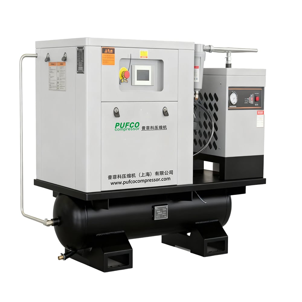
Core Applications of Centrifugal Gas Compressors in Power Generation
A centrifugal gas compressor is a vital asset in power generation, delivering high-volume, continuous gas flow with minimal pulsation. These compressors are central to two critical plant functions: integrating with gas turbine fuel systems and steam-turbine-driven compressor trains, and enabling turbine inlet air cooling (TIAC) to boost output during hot-weather peaks.
Integration with Gas Turbines and Steam‑Turbine‑Driven Compressor Trains
In gas-fired power plants, a centrifugal compressor supplies fuel gas at high pressure ratios and steady flow rates to ensure stable combustion and optimal turbine performance. It may be directly coupled to the gas turbine shaft or driven by an electric motor. In combined cycle configurations, steam turbines often drive centrifugal compressors—converting exhaust heat into mechanical power for compression and reducing the plant’s parasitic electrical load. This waste-heat recovery raises overall efficiency, while the centrifugal design’s ability to handle large volumes with few moving parts supports rapid load following. Operators modulate speed using inlet guide vanes or variable-frequency drives to maintain required pressure ratios across fluctuating fuel demands, improving fuel flexibility, lowering emissions, and ensuring reliable part-load operation. Modern packages integrate advanced anti-surge controls to protect the machine during abrupt load changes—enhancing availability and extending service intervals.
Enabling Turbine Inlet Air Cooling (TIAC) for Output Augmentation
Gas turbine power output drops significantly when ambient temperatures rise because hot air is less dense. TIAC systems use a centrifugal gas compressor to chill inlet air, increasing mass flow into the turbine. In a mechanical vapor-compression cycle, the compressor circulates refrigerant, rejecting heat to a cooling tower or air-cooled condenser. Lowering inlet air temperature by 10–20 °C can raise power output by 10–15% (EPRI, 2021). This augmentation is especially valuable during peak demand periods, when electricity prices are highest. The centrifugal compressor’s compact footprint and large volumetric flow capacity make it practical for both new builds and retrofits. Tight speed control matches cooling output to real-time turbine needs—avoiding surge while maximizing efficiency—resulting in measurable improvements in heat rate and reduced CO₂ emissions per megawatt-hour, without increasing fuel burn.
How Centrifugal Gas Compressors Work: Thermodynamics and Flow Dynamics
Energy Transfer Across Impeller, Diffuser, and Volute Stages
A centrifugal gas compressor converts kinetic energy into potential energy through a precise sequence of aerodynamic components. Gas enters the impeller eye axially and accelerates radially outward due to high-speed rotation, sharply increasing its kinetic energy in accordance with Bernoulli’s principle. The impeller alone typically raises pressure by a factor of 1.5 to 2.5, depending on tip speed. High-velocity flow then enters a stationary diffuser—vaned or vaneless—where expanding flow area decelerates the gas, converting kinetic energy into static pressure. Diffusers achieve a typical pressure recovery coefficient of 0.7 to 0.9. Finally, the volute casing collects pressurized gas and guides it smoothly to the discharge nozzle, recovering additional pressure. In balanced designs, static pressure rise in the impeller roughly equals that in the diffuser. Single-stage units can deliver up to 1,500 cfm at 125 psig, with isentropic efficiencies peaking near 85% (Anglian Compressors, 2023).
Thermodynamic Response to Ambient Conditions, Load Variability, and Altitude
Centrifugal gas compressor performance is highly sensitive to ambient conditions. Higher inlet air temperature reduces gas density, lowering mass flow and output power—roughly 2–3% per 10°F rise. At high altitudes, lower atmospheric pressure further reduces density, often requiring more stages to sustain the same pressure ratio. Load variability also affects efficiency: operation away from the design point risks flow separation and surge. Modern control systems adjust inlet guide vanes and rotational speed to maintain optimal incidence angles. To counter altitude effects, some plants oversize the compressor or incorporate intercooling. Isentropic efficiency can vary by 5–10% across a typical operating range—highlighting the need for site-specific sizing. For gas turbine applications, inlet air cooling helps offset thermal losses, maintaining output during hot days; similarly, high-altitude operation may require turbine derating to prevent compressor surge.
Optimizing Centrifugal Gas Compressor Performance for Plant Reliability
Surge Prevention, Speed Modulation, and Real-Time Load Matching
Centrifugal gas compressor reliability hinges on avoiding surge—a destructive flow reversal occurring when discharge pressure exceeds the machine’s ability to sustain forward flow. The surge line defines the minimum stable flow limit; operation to its left causes violent oscillations and potential damage. Inlet guide vanes (IGVs) extend the stable operating range to lower flows without triggering surge. Speed modulation via variable-frequency drives adjusts impeller velocity instantaneously, matching demand and reducing energy waste. For example, a gas turbine-driven compressor train supplying fuel gas can respond to grid demand signals, keeping the operating point safely within the stable region despite flow fluctuations. Real-time load matching integrates pressure and flow sensors with fast-acting anti-surge valves that recycle gas when approaching the surge limit—ensuring continuous, stable operation. This integrated approach enables peak efficiency across variable loads while safeguarding plant uptime.
Design, Sizing, and Operational Advantages of Centrifugal Gas Compressors
Critical Sizing Parameters: Mass Flow, Pressure Ratio, and Polytropic Efficiency
Proper specification of a centrifugal gas compressor begins with three interdependent variables: mass flow, pressure ratio, and polytropic efficiency. Mass flow governs physical dimensions and inlet geometry; pressure ratio determines the number of impeller stages needed; and polytropic efficiency—accounting for internal losses—directly influences energy consumption and discharge temperature. Modern designs achieve polytropic efficiencies above 85% under rated conditions, but parameter mismatches can force operation into surge or choke zones, eroding performance and shortening component life. Accurate sizing therefore requires balanced analysis of all three to ensure the compressor operates near its peak efficiency “island” across expected load ranges.
Inherent Reliability: Fewer Moving Parts vs. Reciprocating and Rotary Screw Alternatives
A centrifugal gas compressor’s reliability stems from its simple, continuous-flow architecture. Unlike reciprocating units—with pistons, crankshafts, and valves—or rotary screw types—with intermeshing rotors—the centrifugal design relies on a single rotating assembly: impellers, shaft, and bearings. This minimizes cyclic stress, vibration, and wear points, yielding longer overhaul intervals and lower routine maintenance costs. The absence of oil-lubricated compression chambers also eliminates lubricant carryover risk—a critical advantage where contaminant-free process gas or air is required.
FAQ Section
What is the primary function of a centrifugal gas compressor in power generation?
Its primary function is to deliver high-volume, continuous gas flow with minimal pulsation for stable turbine operation and energy efficiency.
Why are centrifugal compressors preferred for turbine inlet air cooling?
They provide compact design and high volumetric flow capacities, enabling effective cooling without increasing fuel burn.
How do centrifugal gas compressors avoid operational surge?
Modern systems employ inlet guide vanes, speed modulation, and anti-surge valves to maintain stable operation and prevent flow reversals.
What makes centrifugal compressors more reliable than reciprocating types?
They have fewer moving parts, reducing wear and maintenance costs while ensuring longer service intervals.

