By PUFCO
An oil-free CO2 compressor raises the pressure of carbon dioxide gas for recovery, transfer or reuse with a design that does not supply lubricating oil to the gas compression chamber. To choose one, start with the gas composition, inlet pressure and temperature, required flow, and delivery pressure. Motor power alone is not enough to identify a suitable machine.
For a recovery project, the most useful question is: Can this compressor deliver the required gas flow throughout the actual operating cycle? A machine that meets a nominal pressure rating may still be unsuitable when the inlet pressure falls, the gas contains liquid droplets, or the receiving pressure changes.
This guide explains the information to collect before comparing models or requesting a quotation.
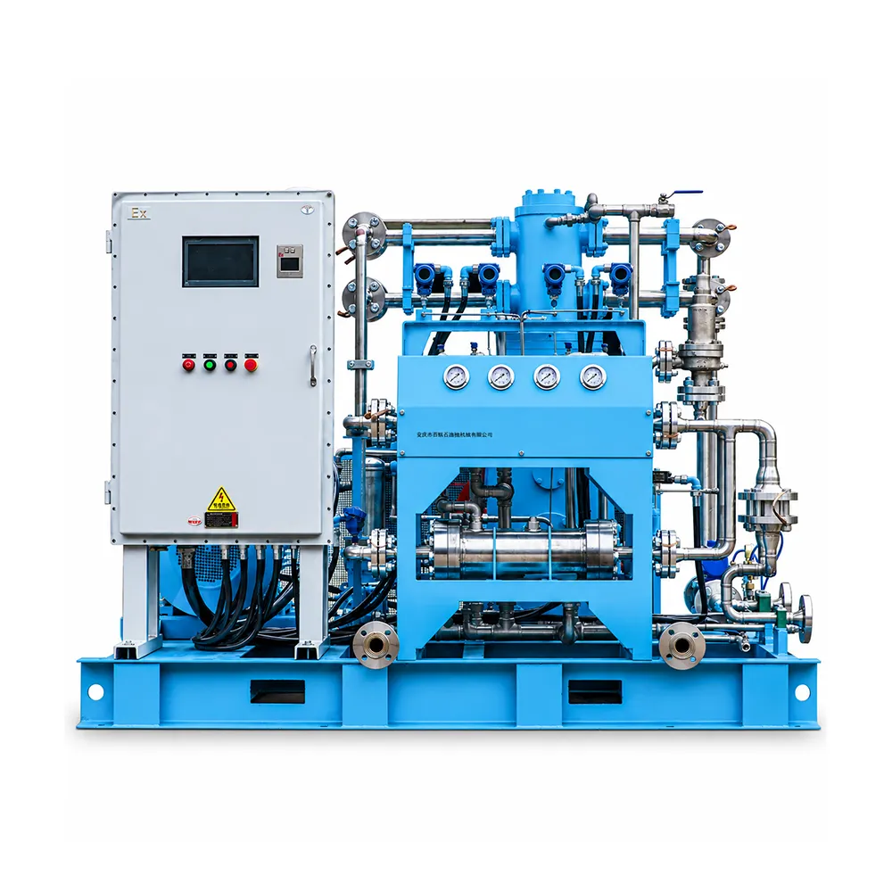
In an oil-free design, lubricating oil is not supplied to the gas compression chamber. Depending on the design, other parts of the machine may still require lubrication. Confirm the gas-path design, separation arrangements and maintenance requirements with the supplier.
Oil-free compression also does not automatically produce food-grade, beverage-grade or pharmaceutical-grade carbon dioxide. The incoming gas can already contain moisture, hydrocarbons or other impurities. The required gas specification, upstream treatment and verification method must be defined separately.
If your process has an oil-content limit, put the limit and test method in the inquiry. A measurable requirement is more useful than asking only for “clean CO2.”
A CO2 recovery compressor can provide the pressure increase needed to move recovered gas into the next process stage. Applications described for PUFCO's CW series include carbon dioxide gas recovery, process transfer and recovery of CO2 gas from extraction processes.
The compressor handles the gas stream within the recovery system. Depending on the process, separate equipment may be needed for separation, drying, purification, cooling, liquefaction or storage. The compressor alone does not perform all of these functions.
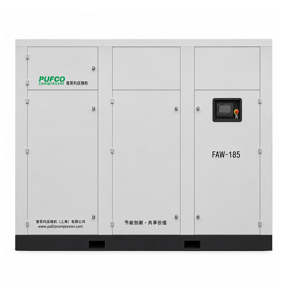
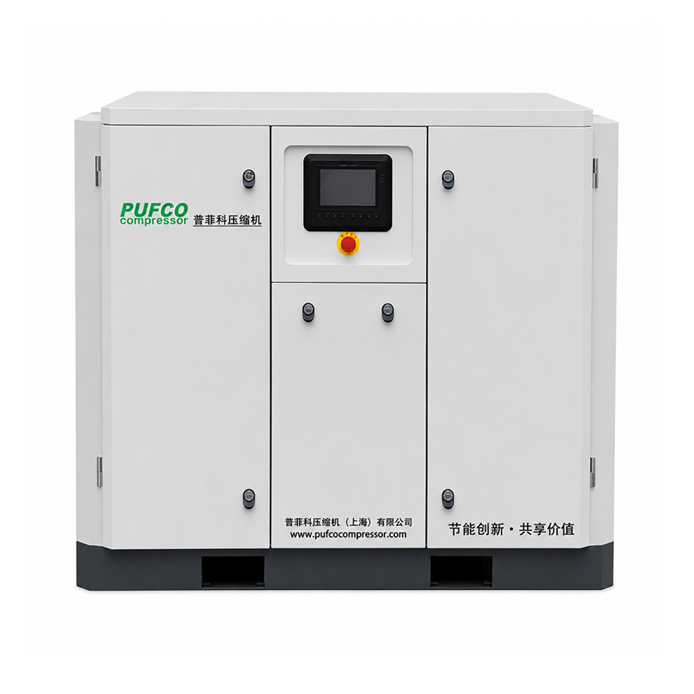
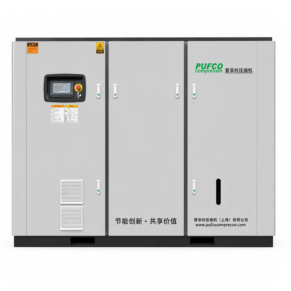
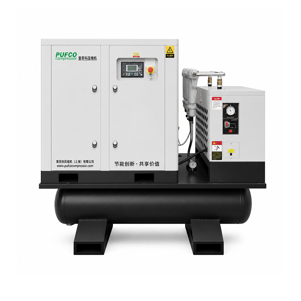
Before comparing equipment, identify the source of the recovered gas and where it must go. Our oil-free CO2 compressor product page lists CW-series configurations and model-specific specifications for an initial comparison.
Provide the CO2 concentration and any known moisture, particles, vapours or other gases. Include a gas analysis when available. These details help the supplier evaluate materials, seals, upstream treatment and operating limits.
State the inlet temperature range and whether liquid carryover is possible during startup, normal running or shutdown. A gas compressor should not be assumed suitable for liquid CO2 or a two-phase stream. Ask how the proposed system keeps the inlet within the approved gas-phase operating conditions.
An inlet pressure range is especially important in batch recovery. As the source vessel empties, suction pressure can fall, changing gas density, available capacity and the compression duty. Ask for capacity at the lowest required suction pressure, not just at the most favourable point.
Always label pressure as gauge or absolute. For example, write bar(g) or bar(a) rather than simply bar.
For an illustrative calculation, consider an inlet pressure of 1 bar(g) and an outlet pressure of 20 bar(g). Using an approximate atmospheric pressure of 1 bar, the overall pressure ratio is:
(20 + 1) ÷ (1 + 1) = 10.5
Dividing the gauge readings would give 20, which is the wrong basis. This example explains pressure notation; it does not determine motor power, stage count or an operating setpoint.
Specify whether the target is a mass flow, such as kg/h, or a volumetric flow, such as Nm³/h. For normal or standard volume, state the reference temperature, pressure and whether the gas basis is dry or wet. Do not assume different suppliers use identical reference conditions.
Do not assume that 100 Nm³/h equals 100 actual m³/h at the compressor inlet. Convert between the stated reference conditions and the actual inlet conditions before comparing capacities.
For batch recovery, also provide the amount of gas to recover and the permitted recovery time. Request performance over the suction-pressure range, so the selection reflects the full cycle.
Give the required pressure at the receiving equipment, together with any known pipe, valve and treatment-equipment pressure losses. Identify whether receiver pressure stays constant or rises during filling.
Distinguish the normal operating pressure, required maximum operating pressure and equipment design pressure. The supplier should confirm the selected compressor's operating envelope and protection settings for the complete duty. A high maximum pressure on a catalogue page does not establish capacity at your inlet conditions.
Compression raises gas temperature, so cooling arrangements and temperature limits belong in the specification. Ask what cooling equipment is included and what air or water conditions the package requires.
For pure CO2, the NIST Chemistry WebBook's carbon dioxide phase-change data report a critical temperature of approximately 31°C and a critical pressure of approximately 73.8 bar absolute. These are physical reference values, not recommended compressor settings.
Pressure alone cannot tell you whether CO2 is gaseous, liquid or supercritical. Temperature and composition must also be considered. Near a phase boundary, ask for a property-based assessment of the actual stream rather than treating it as ordinary compressed air.
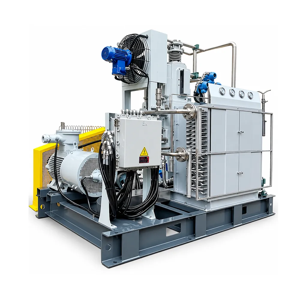
Tell the supplier whether the compressor will run continuously, intermittently or in batches. Include expected operating hours, starts and stops, ambient temperature and installation location.
Confirm the electrical supply, available cooling utilities, space for maintenance and the required documentation for the destination market. PUFCO's published CW-series table lists different motor ratings and electrical options; the exact combination needs to be checked for the selected configuration.
CO2 leak management also belongs in the installation design. The gas can accumulate in poorly ventilated areas and create a dangerous atmosphere. Have the site assessment address ventilation, gas detection and safe discharge locations; a compressor specification does not replace that assessment.
Ask each supplier to quote against the same duty sheet. That makes differences in capacity, package scope and price easier to understand.
| Item to provide | What to clarify |
|---|---|
| Application and source | Recovery, gas transfer or extraction-process recovery; source equipment and receiving system |
| Gas composition | CO2 concentration, known impurities, moisture and available gas analysis |
| Inlet conditions | Minimum, normal and maximum pressure; gauge or absolute basis; temperature range |
| Required capacity | kg/h or volumetric flow with reference conditions; batch quantity and recovery time if relevant |
| Delivery conditions | Required pressure at the receiver, expected pressure changes and known system losses |
| Operation and utilities | Duty cycle, power supply, cooling availability and ambient conditions |
| Package scope | Included cooling, separation, controls, instruments and protection equipment |
| Acceptance and service | Performance basis, required gas quality tests, documentation, spares and maintenance access |
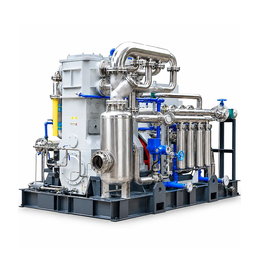
Do not assume an air compressor is suitable simply because its pressure rating looks adequate. CO2 service requires assessment of gas properties, materials, seals, temperature behaviour and the intended operating conditions. Obtain the manufacturer's confirmation for the actual CO2 duty.
No. A gas compressor and a liquid pump are selected for different fluid states. Identify the state at the equipment inlet, including changes during operation, before deciding which equipment your process needs.
No. Oil-free compression does not eliminate inspection, cooling-system care or replacement of wear components. Request the maintenance schedule and recommended spares for the specific design and duty.
It may serve the gas-recovery stage if its operating envelope matches that stage. This does not automatically make it suitable for every high-pressure or liquid-handling part of the extraction process. Supply the process flow diagram and the conditions at the proposed compressor inlet and outlet.
Start with the CW-series carbon dioxide compressor specifications, then send your gas composition, inlet-pressure range, inlet temperature, required flow and delivery pressure.
You can send your CO2 compressor requirements to PUFCO with a process sketch or gas analysis attached. Include your destination country and electrical supply so the proposed configuration can be checked against the installation requirements.
This guide uses PUFCO's published CW-series product information and NIST's carbon dioxide property data. Product photographs come from PUFCO's CO2 compressor gallery. The pressure-ratio example is illustrative; final equipment selection requires confirmation against the actual process conditions.

We use cookies to keep this site working properly and to understand how it is used. You can accept all cookies or continue with essential ones only. Cookie policy
 CN