 CN

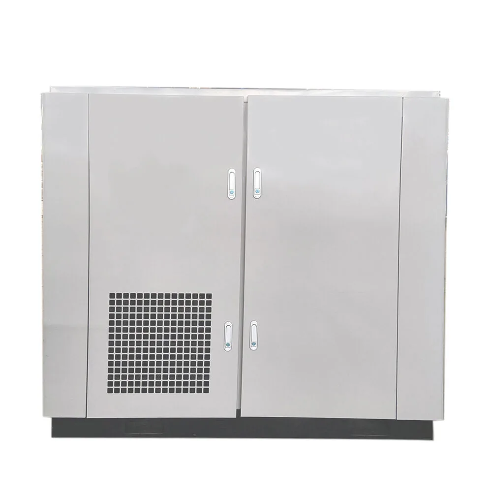
Single-stage Screw Air Compressor
Power:7.5-250kw
Working Pressure:0.75-1.3Mpa
Air Capacity:0.885m³/min-31.3m³/min
Voltage:380V, 110V, 220V,ets
- Overview
- Product Advantages
- Technical Parameters
- Application Scenarios
- FAQ
- Single-stage air end performs the package compression duty.
- Separated internal zones manage heat around electrical components.
- Enclosure treatment helps limit sound transmission during operation.
- Assess demand from equipment expected to run together.
- Confirm model controls and the required operating pressure.
- Specify downstream drying, filtration and storage for use.
Single-Stage Screw Compression for Plant Air
PUFCO single-stage screw air compressors combine a screw air end, motor, cooling system and controls as a packaged industrial air source. Compression takes place in one stage. The series provides a starting point for matching general production air demand to the pressure required by connected equipment.
Internal Heat Zones and Accessible Operating Information
The enclosure separates hotter components from the cooler electrical area and incorporates sound-absorbing material. Pressure and temperature readings are available through the compressor controller for routine observation. Select the package around simultaneous equipment use, then coordinate drying, filtration and storage with the needs of the connected process.
Core Design
Configuration and Selection
Share simultaneous airflow demand, pressure, operating schedule and air-treatment requirements for a quotation.
Why choose our air compressor solutions
Single-Stage Screw Layout
The screw air end completes compression in a single stage. This gives the series a clear role in general plant air supply, with the package selected around the required pressure and consumption.
Separated Internal Heat Zones
The internal arrangement separates hotter components from the cooler electrical area. Managing these zones helps limit heat exposure around the controls and is a practical feature to consider when planning service access.
Precision Rotor Construction
Precision-machined rotors support stable air production at the compression core. Their geometry and manufacturing accuracy help the air end deliver the consistent compression action needed for general production air supply.
Operating Condition Monitoring
Multiple pressure and temperature sensors supply the compressor controller with running information. Staff can review unit conditions through a dedicated interface when managing production air and carrying out routine checks.
Enclosure Sound Treatment
Sound-absorbing material inside the enclosure is used to reduce sound transmission from the package. It is a design feature for the installation environment, with actual noise assessed for the selected model and operating conditions.
Corrosion-Resistant Construction
Corrosion-resistant components and stainless-steel pipework are used within the package. These material choices address corrosion in internal connections and form part of the machine’s construction and routine inspection planning.
| Model | Power(kW) | Pressure(MPa) | Exhaust Vol. (m³/min) | Size(mm) | Weight(kg) | Outlet Diameter |
| FA-7 | 7.5 | 0.75 | 1 | 850X700X920 | 150 | RP1/2 |
| 0.85 | 1.2 | |||||
| 1.05 | 0.855 | |||||
| FA-11 | 11 | 0.75 | 1.65 | 1000X750X1000 | 240 | RP3/4 |
| 0.85 | 1.5 | |||||
| 1.05 | 1.3 | |||||
| 1.3 | 1.1 | |||||
| FA-15 | 15 | 0.75 | 2.5 | 1000X750X1000 | 240 | RP3/4 |
| 0.85 | 2.3 | |||||
| 1.05 | 2.1 | |||||
| 1.3 | 1.5 | |||||
| FA-22 | 22 | 0.75 | 3.8 | 1180X850X1160 | 310 | RP1 |
| 0.85 | 3.6 | |||||
| 1.05 | 3 | |||||
| 1.3 | 2.8 | |||||
| FA-30 | 30 | 0.75 | 5.5 | 1350X850X1160 | 400 | RP1 |
| 0.85 | 5 | |||||
| 1.05 | 4.2 | |||||
| 1.3 | 3.2 | 1180X850X1160 | 310 | RP1 | ||
| FA-37 | 37 | 0.75 | 6.7 | 1500X1000X1390 | 510 | RP1 1/2 |
| 0.85 | 6.2 | |||||
| 1.05 | 5 | |||||
| 1.3 | 5 | |||||
| FA-45 | 45 | 0.75 | 8.5 | 1500X1000X1390 | 670 | RP1 1/2 |
| 0.85 | 8 | |||||
| 1.05 | 7.6 | |||||
| 1.3 | 6.2 | 1500X1000X1390 | 510 | RP1 1/2 | ||
| FA-55 | 55 | 0.75 | 11.2 | 1900X1250X1560 | 1000 | RP2 |
| 0.85 | 10 | |||||
| 1.05 | 8.2 | |||||
| 1.3 | 7 | |||||
| FA-75 | 75 | 0.75 | 13.2 | 1900X1250X1560 | 1100 | RP2 |
| 0.85 | 12.6 | |||||
| 1.05 | 9.2 | |||||
| 1.3 | 8.9 | |||||
| FA-90 | 90 | 0.75 | 15.6 | 1900X1250X1560 | 1200 | RP2 |
| 0.85 | 15 | |||||
| 1.05 | 12.6 | |||||
| 1.3 | 11.9 | |||||
| FA-110 | 110 | 0.75 | 21.6 | 2300X1470X1840 | 1600 | RP2 1/2 |
| 0.85 | 20 | |||||
| 1.05 | 17.3 | |||||
| 1.3 | 15.5 | |||||
| FA-132 | 132 | 0.75 | 24.8 | 2300X1470X1840 | 1800 | RP2 1/2 |
| 0.85 | 23.2 | |||||
| 1.05 | 19.8 | |||||
| 1.3 | 19 | |||||
| FA-160 | 160 | 0.75 | 29.6 | 2300X1470X1840 | 2000 | RP2 1/2 |
| 0.85 | 27.6 | |||||
| 1.05 | 23.2 | |||||
| 1.3 | 23.2 | |||||
| FA-185 | 185 | 0.75 | 31.6 | 2540X1640X1840 | 2600 | RP2 1/2 |
| 0.85 | 30.4 | |||||
| 1.05 | 27.6 | |||||
| 1.3 | 26 | |||||
| FA-220 | 220 | 0.75 | 38.8 | 3200X1980X2150 | 3600 | DN100 |
| 0.85 | 37.9 | |||||
| 1.05 | 30.4 | |||||
| 1.3 | 28.6 | |||||
| FA-250 | 250 | 0.75 | 42.5 | 3200X1980X2150 | 3800 | DN100 |
| 0.85 | 40.5 | |||||
| 1.05 | 34.3 | |||||
| 1.3 | 31.3 |
A single-stage screw air compressor can provide general workshop air for pneumatic tools, actuators, and production equipment, either for a dedicated work area or a plant utility network. Size the supply around the equipment that will run together and the pressure needed at each point of use. Storage, drainage, drying, and filtration should be selected with the compressor so the complete system meets the connected equipment’s air requirements.
Frequently Asked Questions
Q1: What is a single-stage screw air compressor?
▼A1: A single-stage screw air compressor raises air pressure through one compression stage. The term does not specify the motor or control method, so it does not automatically mean permanent-magnet drive or variable-speed operation. Confirm the drive and controls separately for the quoted unit.
Q2: Is this an oil-free compressor?
▼A2: No. This product is an oil-injected screw compressor, so it should not be specified as an oil-free compression source. If the process has limits for oil, moisture or particles, define those limits at the point of use and select the complete downstream treatment system accordingly.
Q3: Can I size a screw compressor by motor power alone?
▼A3: No. Select the compressor by its air delivery at the required operating pressure, then use motor power as part of the performance comparison. Check normal and peak demand, the operating schedule, and pressure losses through treatment equipment and piping before choosing a size.
Q4: What ventilation and maintenance space does a screw compressor need?
▼A4: The installation needs clear cooling-air paths and enough room to open service panels and remove maintenance parts. The room layout must allow heat to escape without obstructing the compressor's air inlet or outlet. Use the selected model's installation drawing and heat-rejection requirements to set clearances and ventilation; the cabinet footprint alone is not the required installation space.
Q5: When should a two-stage alternative be compared?
▼A5: Compare a two-stage option when evaluating the operating efficiency of a significant air load. Use the same pressure, air delivery, inlet conditions, and running schedule to assess the complete packages fairly.
Have more questions about this product? Click the chat icon in the bottom-right corner to contact our team.